Restoring a Dynaco Stereo 70 – Part 1
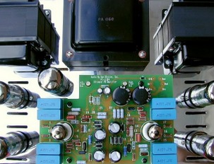 One of the greatest joys of the hi-fi hobby comes from “doing it yourself!” This is especially true when it comes to restoring vintage tube equipment. You don’t have to be a rocket scientist, or even have a degree in electronics in order to bring a 40- or 50-year old amplifier back to a long and healthy future life. You don’t need a fleet of fancy, expensive test equipment either. All it takes is a good soldering iron, an inexpensive multimeter, a few simple hand-tools, and some basic skills that you can easily master.
Note: the very first thing to understand is that all vintage tube amplifiers produce high voltages that can easily kill you!!! Always maintain a healthy respect for the circuitry and voltages involved. After all, you want to live long enough to actually enjoy the music your amplifier will produce. With that little caution out of the way, let’s take a look at the most popular tube amplifier of all time: the Dynaco Stereo 70.
Dynaco, as a company, began in David Hafler’s mother’s kitchen! There, David Hafler and Herb Keroes hand-wound output transformers on the kitchen table. (The history of Dynaco can be found at Greg Dunn’s wonderful website.) David had pioneered a special winding technique that resulted in transformers that had good low-frequency response and good high-frequency response. At the time, this was very unusual, especially for inexpensive transformers. This made it possible to manufacture high-quality amplifiers with relatively simple circuitry and a low parts count. That, in turn, meant that Dynaco could produce amplifiers at a “bargain-basement” price. And produce them they did! Dynaco’s first tube amplifier was the Mark II monaural amplifier that pumped out 50 watts of low-distortion sound.
In 1959, Dynaco embraced the “Stereo Revolution” with the Stereo 70: a 2-channel tube amplifier that went on to sell more than 300,000 units! In kit form, it sold for just $99.95 and it is the best-selling amplifier of all time – even today! In fact, the Stereo 70 has gone on to have a life of its own long after the original Dynaco company ceased to be! You can even buy a new Stereo 70 today (of course, the price is a little higher nowadays!).
If you were lucky enough to “score” a “bone-stock” Stereo 70 from eBay, chances are you won’t be very happy if you simply plug it in and try to listen to it for any length of time. The most likely result will be an amplifier that hums a lot, or worse, one that melts output tubes in very short order. You could even wind up with a shorted or open power transformer! To keep that from happening (and to really understand exactly why the Stereo 70 is such a great amplifier), it will pay you big dividends to “bite the bullet” and rebuild it!
Unlike almost all of the other hi-fi manufacturers of the time, Dynaco always kept the price of their equipment as low as humanly possible! In order to accomplish this, certain compromises were made that simply must be addressed if you want an amplifier that will operate reliably for years to come. After all, Dynaco never expected people to be enjoying their equipment fifty years later! At best, Dynaco equipment was designed for a ten-year life-span. It is a testament to their original designs that any of their gear is still operating at all!
Before we get started, you will need to download a copy of the original Dynaco construction manual. (You can find a copy of the manual at Joe Curcio’s “Dynaco Doctor Forum.”) This manual, like all of the manuals during Dynaco’s “classic period,” was written by the late Bob Tucker. By following the manual carefully, you too can build a Stereo 70 “from the ground up.” Of course, before you can build one, you’ll need to “un-build” your eBay acquisition.
Un-building an original Stereo 70
Only simple hand tools are required. You will need a medium flat-blade screwdriver, a pair of diagonal cutters, a pair of long-nose pliers, a good soldering iron and a good method of de-soldering. A vacuum type “solder sucker” is useful for the dis-assembly. “Solder-Wick” style de-soldering braid can help clean the solder from any terminals that will be re-used. If you plan to refurbish more than this Stereo 70, an electrical de-soldering gun that uses a self-contained vacuum pump is a worthwhile investment. I use a Hakko model 808 de-soldering gun, and while it is a bit pricey (around $169.00 from Amazon.com), it is a real time-saver!
If you have an early Stereo 70, it will have cloth-covered transformer wires. After 50 years, these wires will be quite brittle, so be very careful with them. Later versions of the Stereo 70 will have pvc insulation on the transformer wires. While this insulation is probably less likely to be damaged, use care. If any wire insulation happens to crack, cover the original wires with insulated tubing before you re-install the transformers. This is especially important with the power transformer wiring, since it carries over 700 Volts on some of those wires!
If you have powered up your Stereo 70, make sure that you discharge the can capacitor before you begin your unsoldering. Since you will be replacing it, you can simply ground the four sections of the capacitor to the ground lug of the capacitor can. While it is unlikely that the capacitor will still have a charge on it, it’s better to be safe than sorry.
Begin your dis-assembly by unsoldering the wires of the two output transformers. Wrap a small tag around each wire that connects to the tube sockets because the color-coded wires are most probably impossible to differentiate after all these years. If there is a little extra length available on these wires, you may simply cut them where they connect to the tube sockets and the can capacitor.
Once both transformers have been completely disconnected, you may unscrew the eight mounting screws and carefully remove them from the chassis. Carefully unsolder the two 15.6 0hm resistors from two of the octal sockets and save the resistors for later re-use. (Although you may decide to replace them. We’ll cover this later when we rebuild the amplifier.)
Next, carefully unsolder the wires from the power transformer. Again, leave as much wire length as possible and be very careful with the insulation on the wires. Once all of the wires have been unsoldered, you may un-bolt the power transformer and remove it from the chassis. Make sure you save the two U-shaped clamps that are used to keep the wiring neat and tidy. Unsolder the two wires from the filter choke – again, leaving as much wire length as possible.
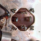
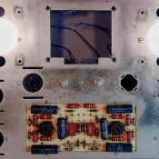
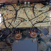
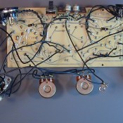
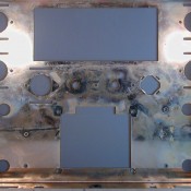
Now, take a close look at your amplifier. If it was factory-wired, the tube sockets, the input and output terminal strips, the long bias supply terminal strip and the common ground lug will all be riveted to the chassis. You will need to drill out the rivets from the five tube sockets on the top of the chassis so they can be replaced. It is not necessary to replace the sockets on the front of the chassis, so they may be left “as-is.”
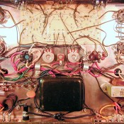
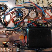
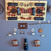
If you have a kit-built amplifier, things are a lot easier. Simply un-screw all of the remaining parts and remove them as a unit. Un-solder all wires from the Driver Board, the bias potentiometers and remove all remaining parts from the long terminal strip. Be careful when you remove the three-legged capacitor – you might want to re-use it later. Examine the seven octal sockets and select the two nicest ones for re-use as the front panel “biaset” sockets. Refer to the picture in order to see which other parts you should retain for possible re-use.
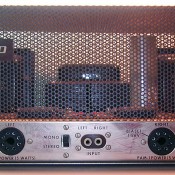
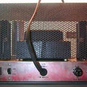
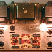
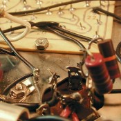
Click on any image below to view a slide show of the “un-building” process…!
Congratulations! You have now “un-built” your Stereo 70! But, there’s still a good bit of work to be done before we can start following the construction manual to rebuild the amplifier. We will need to “un-build” and rebuild the driver board assembly. We’ll get to that in a moment, but first, remove the stereo-mono switch and the power switch. Again, if your amplifier was factory-wired, you will have to drill out the rivets used to mount these switches. If your fuse holder is in good condition, it can be re-used. If your Stereo 70 was a kit-built unit, you can remove the rest of the remaining parts on the chassis and give the chassis a thorough cleaning. Caig deoxIT is a great product for cleaning the entire chassis. Be careful with any of the lettering that remains on the chassis. It is very easy to damage it with solvents.
Obtaining parts for the driver circuit rebuild
Once the chassis is as clean as possible, set it aside and get ready to “un-build” the driver board assembly. But before we can rebuild anything, we’ll need to decide whether to rebuild using carbon-composition resistors, or more modern metal-film resistors. Either method will yield satisfactory initial results, but long-term reliability will be improved if you decide to go with modern metal-film resistors. If you do decide to go with carbon-composition resistors, I strongly recommend that you use NOS Allen-Bradley carbon-composition resistors. Since Allen-Bradley stopped manufacturing these resistors in 1991, prices have been rising steadily. It is not uncommon to find 1/2 watt 5% Allen-Bradley carbon-composition resistors selling for up to $2.00 each! Make sure you measure each and every carbon-composition resistor before you install it. For optimum results, resistors should be closely matched between channels. For example, the driver board uses two 620 ohm resistors; one for each channel. It’s absolutely fine if these resistors are plus or minus 5% of their nominal value, but both resistors should be as close to the same value as possible. This will help to maintain the same gain and frequency response between channels. This might require checking many individual resistors in order to find two that match each other and at current prices, this can become prohibitively expensive, quickly. You may need to go through 25 resistors in order to find two that are within 1% of each other!
Fortunately, this is not the case with Vishay/Dale metal film resistors. (And they will be a lot cheaper to purchase than “classic” Allen-Bradleys!) In order to make your parts ordering simpler, here is a complete list of parts, sources and current prices for each part you will need to completely rebuild a Stereo 70. All prices are in US Dollars. The only parts that will be re-used are the three transformers and the filter choke. (If your filter choke requires replacement, new ones are available from www.dynakitparts.com for $12.50, plus shipping.)
----------------------------------------------------------------------------------------------------------------------------
Quantity  Value           Description                     Source             Part Number             Mfr            Price
----------------------------------------------------------------------------------------------------------------------------

                                                          Resistors

----------------------------------------------------------------------------------------------------------------------------
   2	   10 ohms        10 ohm 1/2 watt resistor        Mouser             71-CMF6010R000FHEK      Vishay/Dale    $  .12
   2       15.6 ohms      precision resistor              Dynakitparts.com   BRWW-15D6               Unknown        $ 4.25
   2       47.5 ohms      47.5 ohm 1/2 watt resistor      Mouser             71-CMF6047R500FHEK      Vishay/Dale    $  .12
   2       619 ohms       619 ohm 1/2 watt resistor       Digi-Key           CMF619HFCT-ND           Vishay/Dale    $  .16
   4       1000 ohms      1000 ohm 1/2 watt resistor      Mouser             71-CMF601K0000FHEK      Vishay/Dale    $  .12
   2       1000 ohms      1000 ohm 1 watt resistor        Digi-Key           PPC1.0KW-1CT-ND         Vishay/BC      $  .348*
   2       5.1 K          5.1 K ohm 1 watt resistor       Digi-Key           PPC5.1KW-1CT-ND         Vishay/BC      $  .348*
   1       6.8 K          6.8 K ohm 1 watt resistor       Digi-Key           PPC6.8KW-1CT-ND         Vishay/BC      $  .348*
   2       18.2 K         18.2 K 1/2 watt resistor        Digi-Key           CMF18.2KHFCT-ND         Vishay/Dale    $  .16
   2       18 K           18 K 1 watt resistor            Digi-Key           PPC18KW-1CT-ND          Vishay/BC      $  .348*
   1       22 K           22 K 1 watt resistor            Digi-Key           PPC22KW-1CT-ND          Vishay/BC      $  .348*
   4       47 K           47 K 1 watt resistor            Digi-Key           PPC47KW-1CT-ND          Vishay/BC      $  .348*
   4       270 K          270 K ohm 1/2 watt resistor     Digi-Key           PPCHJ270KCT-ND          Vishay/BC      $  .59*
   2       270 K          270 K 1 watt resistor           Digi-Key           PPC270KW-1CT-ND         Vishay/BC      $  .348*
   2       330 K          330 K 1 watt resistor           Digi-Key           PPC330KW-1CT-ND         Vishay/BC      $  .348*
   2       475 K          475 K ohm 1/2 watt resistor     Digi-Key           CMF475KHFCT-ND          Vishay/Dale    $  .16
   2       1.5 Meg        1.5 Meg 1/2 watt resistor       Digi-Key           CMF1.50MHFCT-ND	     Vishay/Dale    $  .91
----------------------------------------------------------------------------------------------------------------------------

                                                          Capacitors

----------------------------------------------------------------------------------------------------------------------------
   2       82 pF          82 pF 500 Volt mica Capacitor   Mouser             598-CD15ED820J03F       Cornell/Dub.   $  .76
   2       390 pF         390 pF 1000 Volt mica Capacitor Mouser             598-CDV16FF391JO3       Cornell/Dub.   $ 2.02
   2       0.022 uF       0.022 uF 630 Volt Capacitor     Digi-Key           P12125-ND               Panasonic/NTE  $ 1.21
   2       0.047 uF       0.047 uF 630 Volt Capacitor     Digi-Key           P12142-ND               Panasonic/NTE  $ 1.44
   4       0.1 uF         0.1 uF 630 Volt Capacitor       Digi-Key           P12158-ND               Panasonic/NTE  $ 1.55
   4       1.0 uF         1.0 uF 630 Volt Capacitor       Digi-Key           P12276-ND               Panasonic/NTE  $ 2.40
   1       80/40/30/20 uF Multi-Section Can Capacitor     Dynakitparts.com   284320-2                CE             $34.95**
   2       100 uF         100 uF 100 Volt Capacitor       Mouser             594-2222-138-31101      Vishay/BC      $ 1.72
----------------------------------------------------------------------------------------------------------------------------

                                                          Diode

----------------------------------------------------------------------------------------------------------------------------
   1       1N4007         1 Amp 1000 P.I.V. diode         Digi-Key           1N4007DICT-ND           Diodes Inc.    $  .30
----------------------------------------------------------------------------------------------------------------------------

                                                          Switches

----------------------------------------------------------------------------------------------------------------------------
   1       SPST Switch    Standard Slide Switch           Radio Shack        275-401                 Unknown        $ 2.99
   1       DPDT Switch    Standard Slide Switch           Radio Shack        275-403                 Unknown        $ 2.99
----------------------------------------------------------------------------------------------------------------------------

                                                          Sockets, Terminal Strips and Connectors

----------------------------------------------------------------------------------------------------------------------------
   1       Dual RCA jack  With Insulator                  Dynakitparts.com   RCA-2-STD               Unknown        $ 3.50
   2       Output Strip   Brown - original style          Dynakitparts.com   TERMSTRIP               Unknown        $ 2.50
   1       Terminal Strip 2 terminals                     Dynakitparts.com   TS-2LUG                 Unknown        $  .75
   5       Octal Sockets  Cinch Style                     Dynakitparts.com   8PSCM-BRU-LS            Unknown        $ 4.75
   2       9-pin sockets  PC mount                        Dynakitparts.com   9PSPC-CRC               Unknown        $ 1.75
   1       Fuse Holder    3 AG - chassis mount            Dynakitparts.com   FH-3AG-PS               Unknown        $ 3.75
----------------------------------------------------------------------------------------------------------------------------

                                                          Hardware

----------------------------------------------------------------------------------------------------------------------------
   38      #4 screws      pan-head machine screws with lock washers and nuts
   10      #10 screws     pan-head machine screws with lock washers and nuts
   4       #10 nuts and lock washers.
----------------------------------------------------------------------------------------------------------------------------
NOTES:  *  Indicates there is a minimum purchase of five units of this component
        ** Indicates that this part is currently out of stock, but will *probably* be available again soon. A
            higher voltage part is available at additional cost.
============================================================================================================================
Unless otherwise noted, all parts were in stock as of April 23, 2010. If your original chassis is a “rust bucket,” replacement chassis are available from www.dynakitparts.com.
Looking ahead
Let’s take a break for now. In our next installment, we’ll cover completely rebuilding the original driver circuit board assembly. To prepare for that little “adventure,” pick up a bottle of common lighter fluid from your nearby convenience store. You’ll use it to clean the waxy substance from the printed circuit board before you begin unsoldering parts. Original printed circuit board assemblies are extremely fragile. If you don’t clean the wax from the board, circuit traces will almost certainly lift or break when you attempt to remove the original parts.
While it might appear that your Stereo 70 is now a pile of junk, nothing could be further from the truth. You’ve finished the “fun part” of tearing a Stereo 70 apart. Get ready to experience the truly rewarding part. There is no thrill quite like firing up an amplifier you built with your own two hands! It’s an even bigger thrill when it makes beautiful music! You’ll be singing a happy tune very soon. Until next time…


This is an awesome artivle – love the new web site as well!
Keep up the great work!
when is part 2 coming?
now that i’ve torn apart my dynaco stereo 70 i am wondering when you are giong to publish part 2.
Hello, Friends!
Sorry about those infernal delays. Our second part of the Stereo 70 restoration article will be forthcoming. At present, we are shooting for it to appear in the December issue!
My sincere apologies for the delays. I’m afraid that family medical “issues” have shifted me into a “caretaker position” for the past few months, but I am gettin’ geared up for a real FLURRY of activity! Our Stereo 70 project will contain a surprise in the next article. I hope we can answer a “nagging” question.
More to come…
Sincerely,
Bill Thomas
thanks for the great article, it was very precise and am glad to hear the next part is forthcoming. sorry to hear about your family medical issues, hope all is as well as can be. keep up the good work.
None of this major overhauling is necessary and is a waste of time. I got my ST-70 bone stock and replaced the output tubes with a matched quad. It didn’t work on the left side and a tube plate glowed red and I couldn’t set the left side bias. I replaced the coupling caps on the PC board and bypassed the selenium rectifier with a silicon diode. It still didn’t work. It turns out that one of the 15.6 ohm wire wound resistors from terminal 8 to ground was shorted. I replaced both of them and it has been working just fine for four years now. Only replace what needs to be replaced. This amp is still, with the exception of the silicon diode bone stock. If it ain’t broke don’t fix it.
Doug wrote: “None of this major overhauling is necessary and is a waste of time.”
This article is intended for people who want their ST-70 to perform like new (or better) and not be a ticking time bomb, just waiting for a failure of a selenium rectifier, cap, or wiper in a bias pot to destroy matched EL-34 tubes, rare 7199 tubes, or other rare and expensive parts.
If you’re one of those people who just wants background noise and don’t care about the audible degradation that comes from old, dried-out electrolytic capacitors, out-of-spec carbon resistors, and selenium rectifiers which are dropping the forward voltage too much, then enjoy. But have a back-up amp for when some 40 year old part finally gives up the ghost and makes a mess of your amp.
where can i read part 2 ? this was a great help to me when 6 mos ago i bought st 70.
Hi Ed, unfortunately there won’t be a Part 2, as Bill Thomas has passed away.
A couple of decades ago, I acquired many parts related to the Dynaco 70, Four beautiful EL-34s. I even constructed a metal support base for all the components and as far as I know I acquired one of the last set of hand built transformers from a guy at EBay that took about a year to deliver (When I almost thought the money was lost). All these, plus parts, screws, etc. And an empty driver board have been kept all these years in a plastic bin, that survived two marriages, and lot of dream of enjoying it one day. I get excited when I read someone’s page like this, and the dreams aflore.